1 Abstract
In order to calibrate the AuxTel instruments, particularly the LATISS spectrograph, we want to illuminate the focal plane with monochromatic light at a range of wavelengths.
This tech note describes the Rubin Observatory Auxilliary Telescope Calibration Illumination System, its basic operation, maintenance and trouble-shooting, and a test dataset.
2 Overview
The Auxilliary Telescope (AuxTel) Calibration Illumination System will be used to illuminate the white calibration screen in the AuxTel with a tunable light source, ranging in wavelength from 350-1200 nm. The illumination system will sit on the dome floor directly below the calibration screen.
The work to prepare this subsystem for shipment was tracked in the JIRA Epic SITCOM-259c.
Some documentation on this system can be accessed on Docushare Collection-11943.
There are additional details about control of the LabJack in Tech Note 36. An overview of the data is in a Jupyter Notebook in the github for this tech note.
3 System Description
There are five main functional elements of the AuxTel Illumination System:
The White Light Source (WLS) supplies the light, and requires a chiller to remove min-infrared wavelengths (heat) from the beam.
The Monochromator changes the wavelength of the output light.
Optics deliver the light to the calibration screen. There is a shutter that can be opened when using the illumination system.
The Electrometer and Fiber Spectrograph are used to monitor the output beam.
The Electronics Cabinet provides power and control to the other hardware.
These elements are integrated on a large, heavy table. The White light source, monochromator, and optics are all housed in a light tight box.
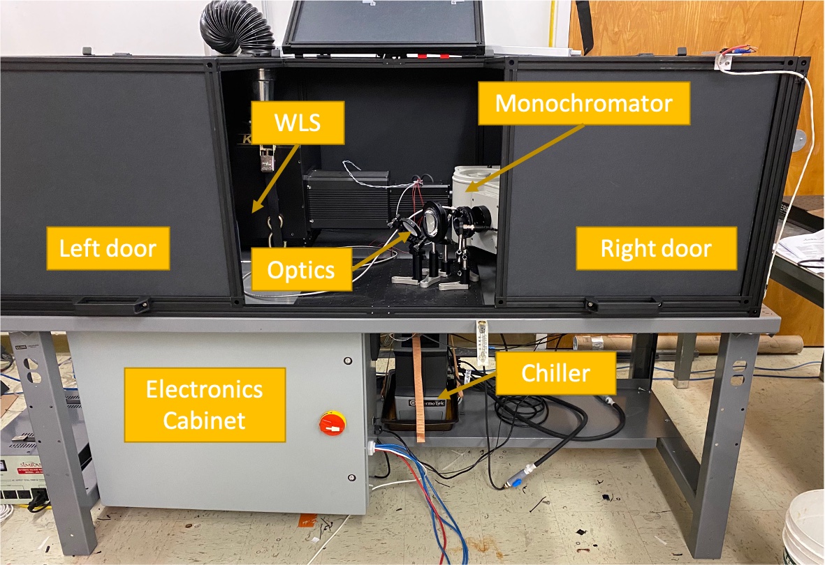
Figure 1 AuxTel Calibration Illumination System setup in the Tucson Lab.
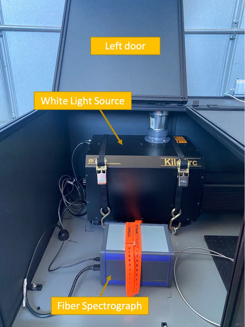
Figure 2 Left side of Illumination as seen in the AT dome.
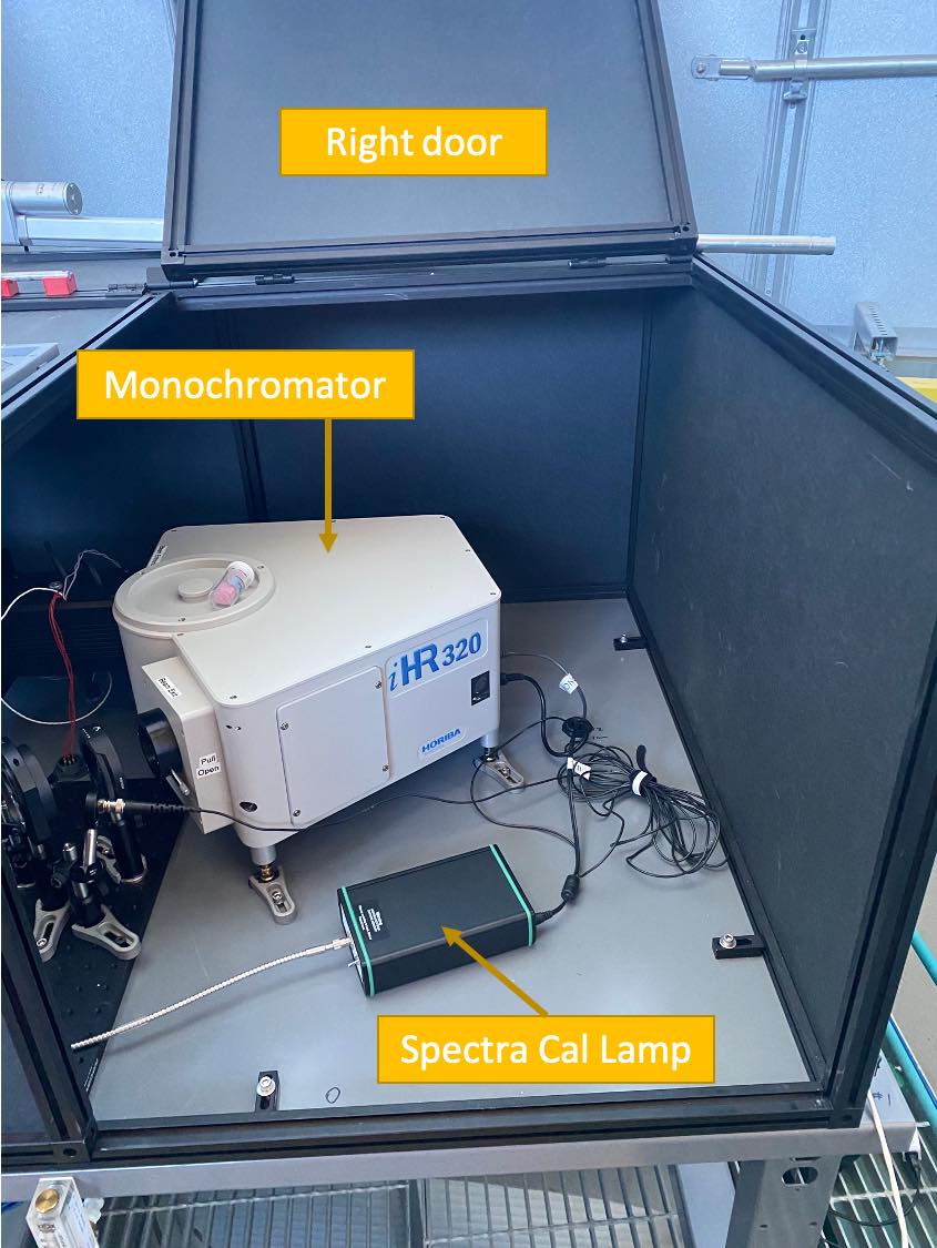
Figure 3 Right side of Illumination as seen in the AT dome.
3.1 White Light Source
The white light source is a KiloArc Lamp built by Optical Building Blocks. It can output white light with a power of 800 - 1200 W. This light is directed into the monochromator.
Because of the heat generated by such a lamp, before sending the light into the monochromator, the light travels through a water cell which absorbs much of the infrared radiation. This water heats up, so the white light source must be operated with a chiller, discussed below. The chiller should keep the water cool enough, but if there is ever a situation where there is either too much heat being sent into the monochromator or the chiller fails, there is a thermal fuse attached to the entrance to the monochromator. When it hits a certain temperature it will trigger the emergency stop.
The WLS will also experience freezing temperatures on the summit. To avoid freezing the water in the cell, there are heaters attached to the cell which will be turned on at a certain temperature, as determined by the operator. The heaters are controlled by an Omron temperature Controller.
Note
The bulb for the WLS is a Mercury-Xenon arc lamp. In the rare case that a mercury bulb explodes and the mercury is released from its envelope, it is recommended that that all personnel should leave the immediate area at once, so that no mercury vapor is inhaled. The area should be ventilated for a minimum of 30 minutes. When the lamp housing has cooled any mercury residue should be picked up with a special adsorptive agent. Compact arc bulbs contain a highly pressurized gas, and present an explosion hazard even when cold. If the lamp goes out, there is a spare bulb available. Please follow the instructions carefully.
The thermal fuses are set to turn off the power at 85C and the heaters will turn on when the cell reaches 5C, warming up the cell to 26C. The temperatures for the heaters are adjustable within the electronics cabinet. In order to change the temperature setting for the thermal fuse, a new fuse will have to be purchased and installed manually.
Note
The heaters and thermal sensor to control the heaters are attached directly to the water cell. If the system needs to be disassembled for any reason, please take care when removing these items.
The white light source can either be manually or remotely controlled. It is important to toggle which mode you are using on the back of the white light source. We use a LabJack to control the WLS, receive errors and set the power. Details on the LabJack control of the WLS are found in tech note 36.
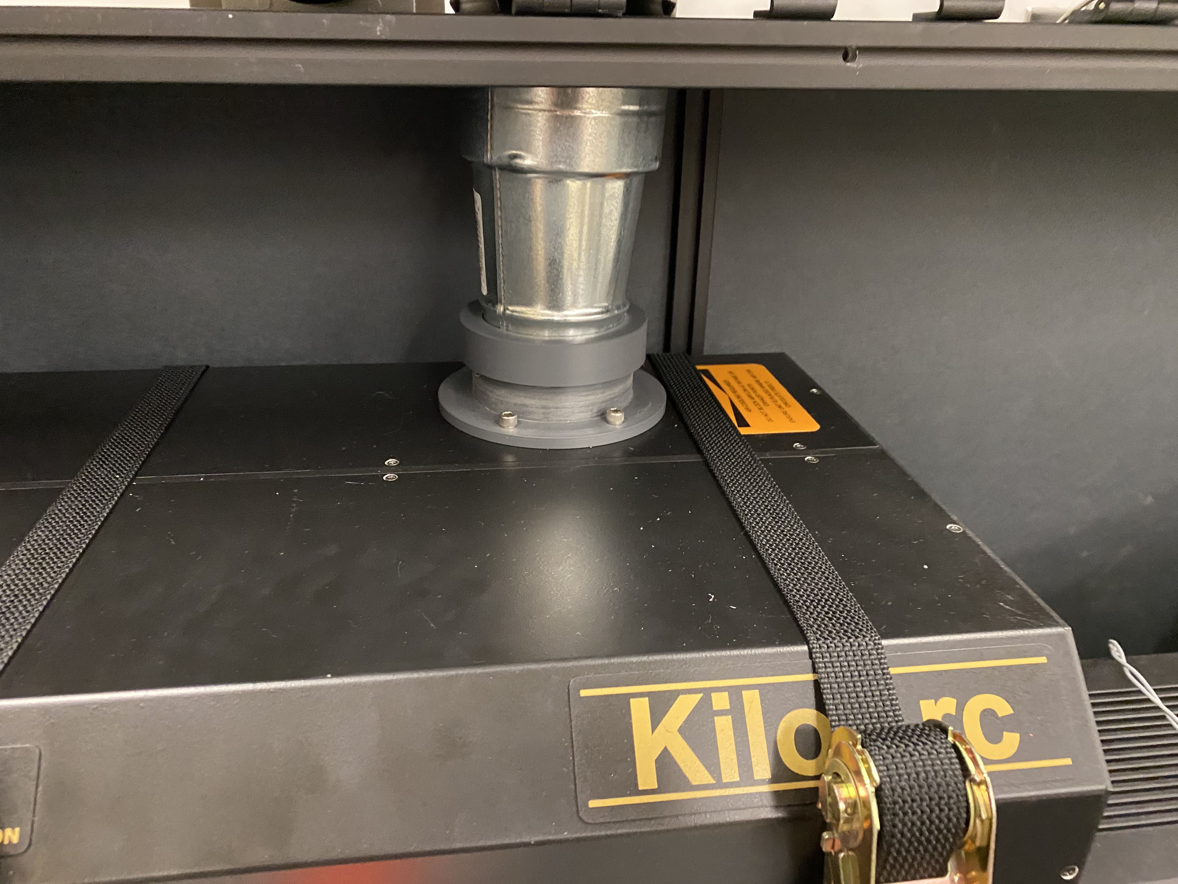
There are two cables that come from the WLS: one for commanding the power level and the other to receive status and error messages. There are fans internal to the WLS which blow air out of a hole at the top. Secured to this hole is an aluminum duct that pushes the air outside of the enclosed area.

The WLS is controlled using the ts_ATWhiteLight CSC. See the XML documentation for more information.
Further documentation on the White Light Source can be found on Docushare here
3.2 Chiller
The chiller is used to cool the water cell in the white light source. This uses a mixture of methanol and water (10/90) to carry heat from a shell surrounding the main water cell. The water should be distilled water, which can obtained from the DI plant that supports the coating chamber. The methonol helps the water in these tubes from freezing. The chiller does not actually pump the water in and out of the cell, but rather carries heat from tubes surrounding the water cell. The control is on the water returning to the chiller so there is likely to be some delay for large temperature swings. The temperature should be set to 25C.
The white light source cannot be turned on until the chiller is running. The chiller must be on for a minimum of 15 minutes after the white light source has been turned off before it can be turned off.
The fluid level of the chiller should be checked occasionally. See the maintenance section below.
The chiller is controlled via a serial device server (RS-232 to ethernet) with the ts_ATWhiteLight CSC.
To setup the Moxa serial device server, follow these steps:
Put the IP address into your browser (auxtel-chiller.cp.lsst.org )
Go to QuickSetup and make sure the following is set:
Select TCP (not Real COM)
9600 Baud, 8 data bits, no parity, 1 stop bit and XON / XOFF flow control
RS-232
Click Save/Restart
If you need to set up a new serial device for the first time, follow the same steps as for the Electrometer, except for the settings in step 7 (use those listed above).
The chiller documentation on Docushare can be found here
Note
The flow of water from the chiller must be kept below 8 GPM, which can be read on the flow meter. To constrict the flow, use the nozzles on the tubes sitting beside the chiller.Additionally, confirm that the pump drive is running at around 50%, not higher. To change/check this value, press the Next button on the screen and select Set Pump Drive.
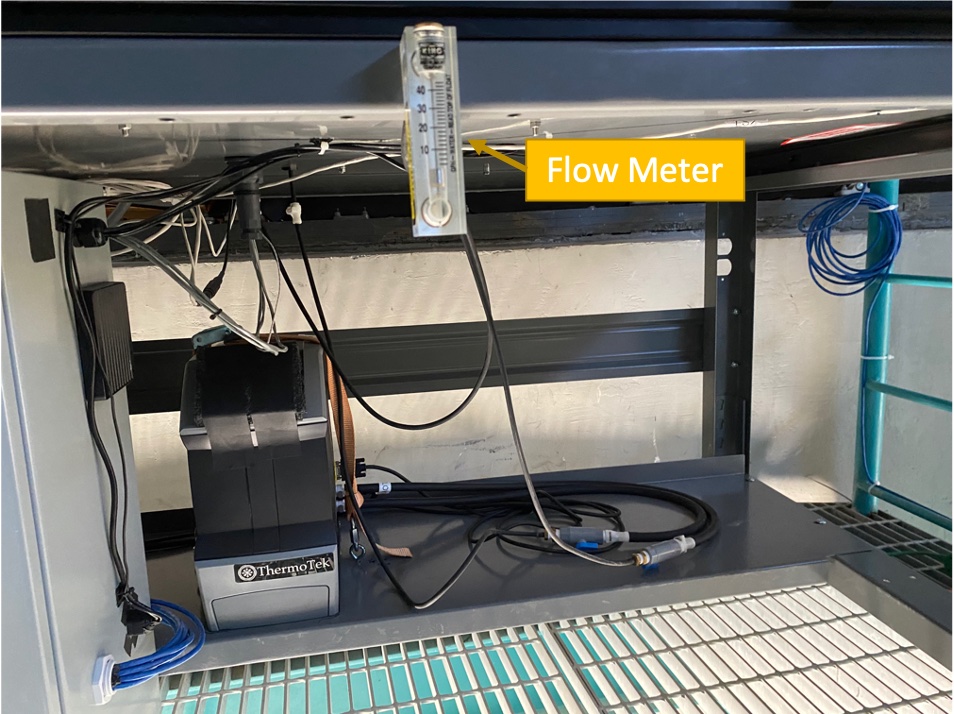
Figure 4 Flow meter for chiller system. Flow level should be less than 8GPH.
3.3 Monochromator
The monochromator is essentially a spectrometer. With the incoming white light, it can output any wavelength from 0 - 1500 nm with fairly high resolution. We will only use it in the range of 350 - 1050 nm, as our chips have essentially zero sensitivity beyond that wavelength. The monochromator is the Horiba iHR 320 Fully Automated Imaging Spectrometer. There are two 1200 gr/mm gratings: one centered at 400 nm (blue) and one at 750 nm (red). These gratings both have a spectral dispersion of \(\sim2.31\) nm/mm. It also includes a mirror. There are two slits, both of which can be adjusted from 0-5mm, excluding 5mm. The “Entry” slit is where the light from the white light source enters the monochromator and the “Exit” is where the light exits the monochromator as a “single” wavelength. The monochromator uses very little power at 12V to change the slit width, the wavelength, and the grating.
The software for the monochromator is run on a Windows Machine, mounted on an Embedded Systems minicontroller. It is connected via USB to this windows machine. When first starting up, the windows machine must be accessed via Remote Desktop for the initialization process. The credentials for the Remote Desktop can be found in the AuxTel 1password Vault. Once that has completed, the ts_monochromator CSC can be used to control the Monochromator.
The monochromator is secured with it’s three feet mounted to the table. They should be adjusted such that the monochromator is level with the white light source.
The manual can be found on Docushare here.
3.4 Fiber Spectrograph
The fiber spectrograph used is an Avantes SensLine AvaSpecULS2048x64TEC-EVO, with a wavelength range of 200-1160 nm. An optical fiber runs from the fiber spectrograph and samples the light from the optical path after it exits the monochromator.
The fiber spectrograph is controlled via USB that runs directly from the fiber spectrograph to a linux control computer (auxtel-ill-control.cp.lsst.org) in the electronics cabinet. It can be commanded by the ts_fiberspectrograph CSC. More information can be found at https://ts-fiberspectrograph.lsst.io.
We also have a fiber illuminator (Spectral Cal Lamp), which can be used to calibrate the Fiber Spectrograph. Power is avaialble for the illuminator on the table, but we expect that the illuminator will only be installed when needed. When we want to calibrate the fiber spectrograph, simply move the fiber from the optical path and install it into the illuminator.
3.5 Electrometer
The electrometer used is the Keithley 6517B. It reads the current from a Hammatsu Si S2281 Series photodiode. The photodiode samples the light on the edge of the optical path after exiting the monochromator. It does not measure the total brightness but rather any changes in irradiance from day to day and even throughout a daily calibration.
The electrometer is controlled via a Serial Device Server, the MOXA Nport 5100. Information on the moxa setup can be found here.
The electrometer can be run in charge or current mode. We recommend running it in current mode for this application. The Electrometer is commanded by the ts_electrometer CSC, which has its configuration stored in ts_config_ocs. See the XML documentation for more information.
The electometer sits in the electronics box and the cable from the photodiode is routed from the top of the table.
Information on the electrometer and photodiode can be found on Docushare here
3.6 Optics
There are three optics that deliver the beam from the monochromator to the calibration screen. The first is a cylindrical lens (CKX20) that shapes the beam and can be rotated. The light then goes to an asphere (Thorlab ACL7560U-A) and then to a fold mirror that reflects the light straight up through the shutter. The optical design for this system can be found on Docushare. This optical design is currently being re-designed and will be replaced.
In the current design, the cylindrical lens should sit 55mm from the exit slit of the monochromator. The asphere should be aligned with the cylindrical lens, and its front face should sit 80mm from it. The mirror should have an ~45deg angle and sit ~56mm from the back of the asphere.
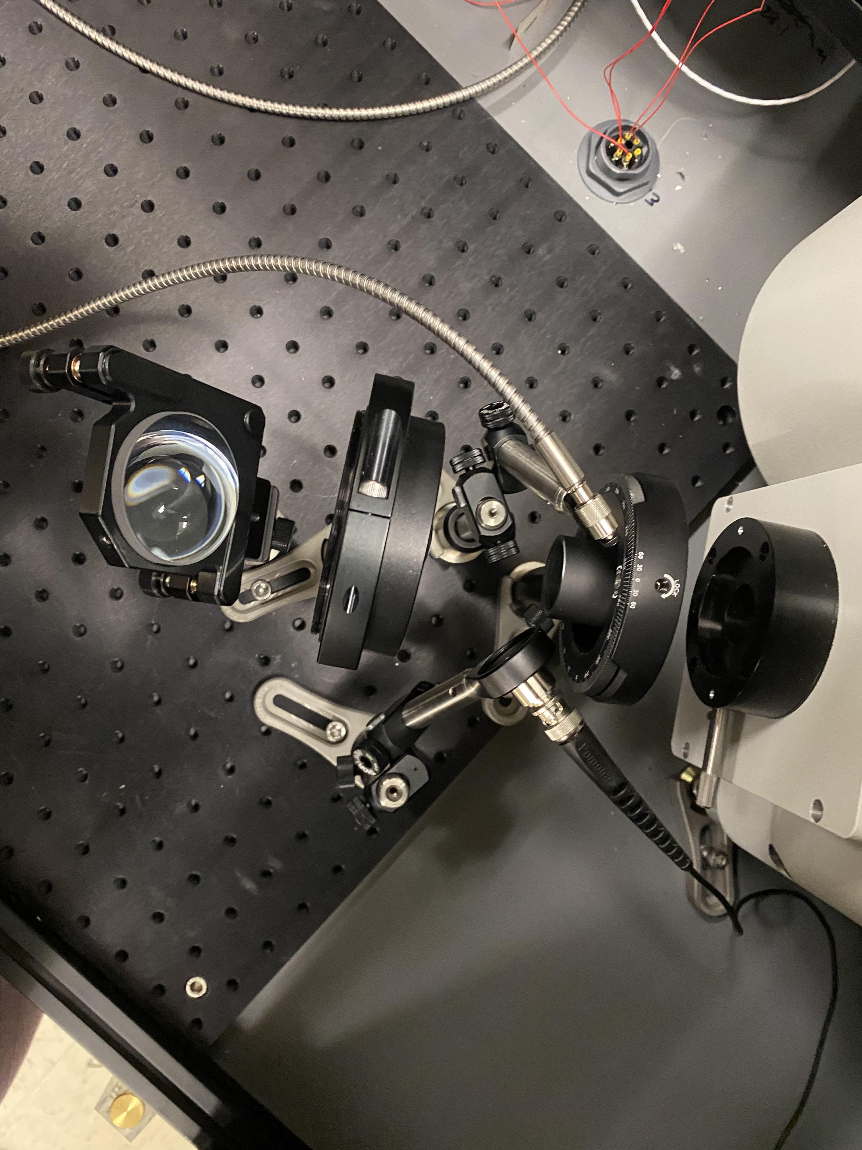
Figure 5 Optics assembled to deliver light from the monochromator to the screen.
3.7 Shutter system
In order to both keep light enclosed when not needed and also to keep dust out of the illumination system, there is a shutter for the output of the beam. The beam travels through glass when the shutter is opened. The shutter can only be commanded fully open or fully closed, not at a point in between. When the shutter has reached one limit or another, it will hit a switch which will confirm to software that it has indeed reached the end of travel. The linear actuator is attached to the top of the structure so must be disassembled before the top of the box can be moved.
The linear actuator that moves the shutter is controlled with the LabJack. More information can be found on that in tech note 36.
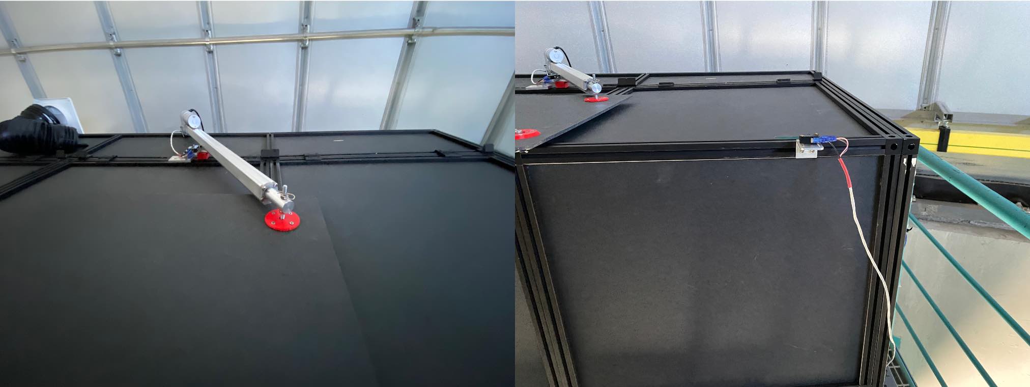
Figure 6 Shutter system contains shutter, linear actuator and two limit switches.
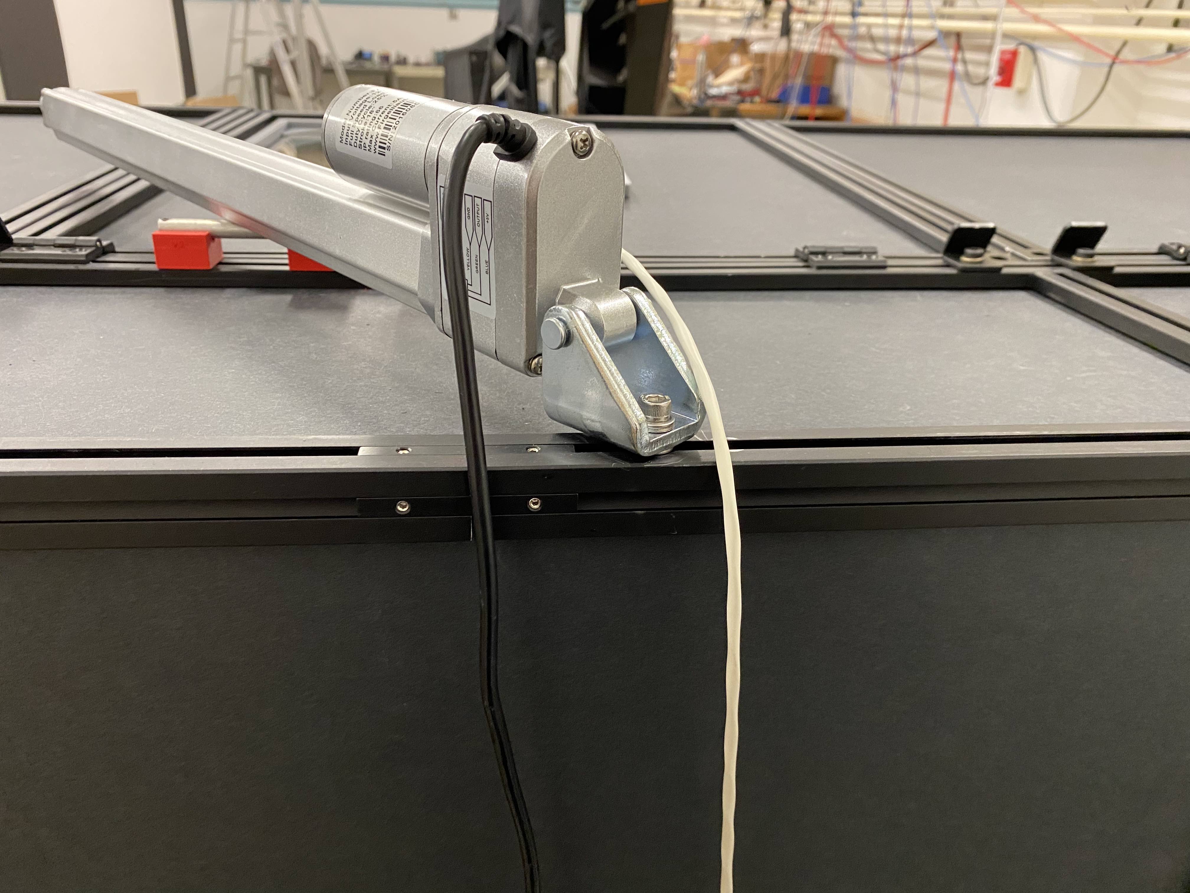
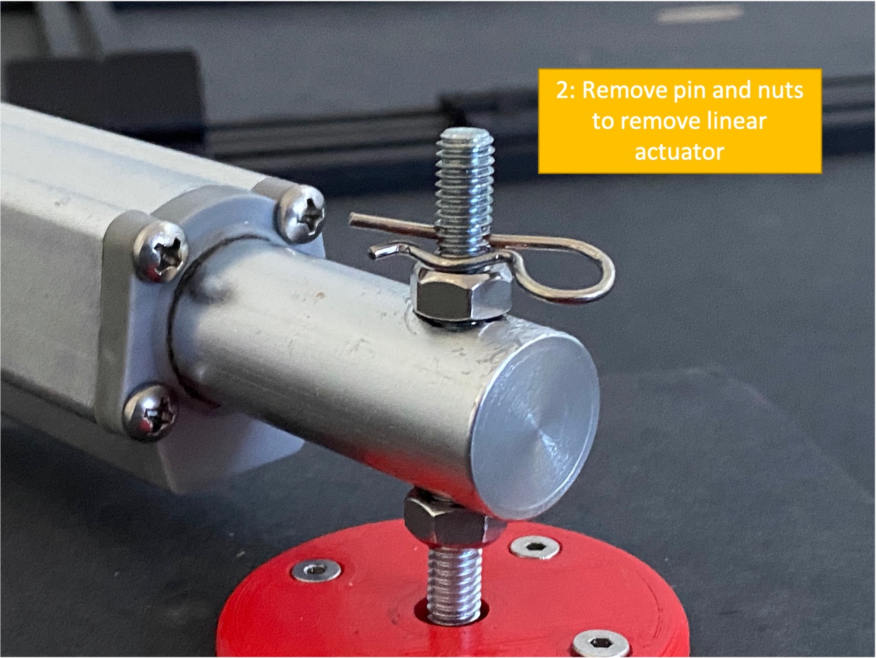
Figure 7 Linear actuator for shutter system.
3.8 Electronics Cabinet
The electronics cabinet must be turned off before opening. Before turning the power off, please be sure to power down the control computer (auxtel-ill-control.cp.lsst.org). Inside the cabinet there is a thermostat and fan that keeps the electronics cooled. The thermostat is set at 20C.
The cabinet includes the control computer (auxtel-ill-control.cp.lsst.org) and the windows machine for the monochromator, both of which are embedded SBCs. There are two serial device servers for the electrometer and chiller and the LabJack with custom board. There are 5V, 12V and 24V voltage supplies, all of which plug into an 8-outlet PDU.
The electronics cabinet is powered by 220Vac from the dome. Additionally, 6 ethernet cables are needed to run into the electronics cabinet for: electrometer serial device server, chiller serial device server, control computer (auxtel-ill-control.cp.lsst.org), monochromator windows machine, LabJack, PDU.
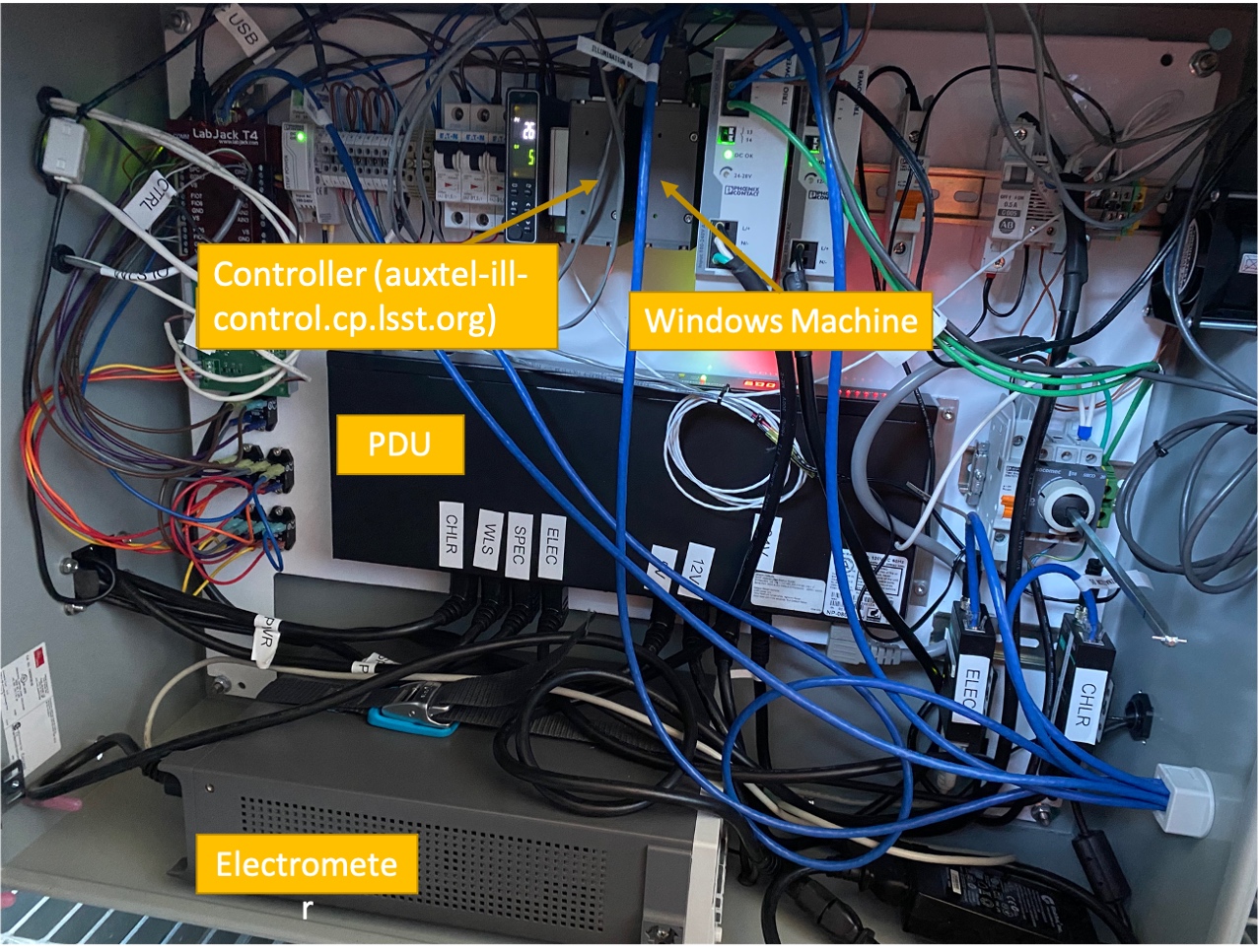
Figure 8 View of electronic cabinet when opened.
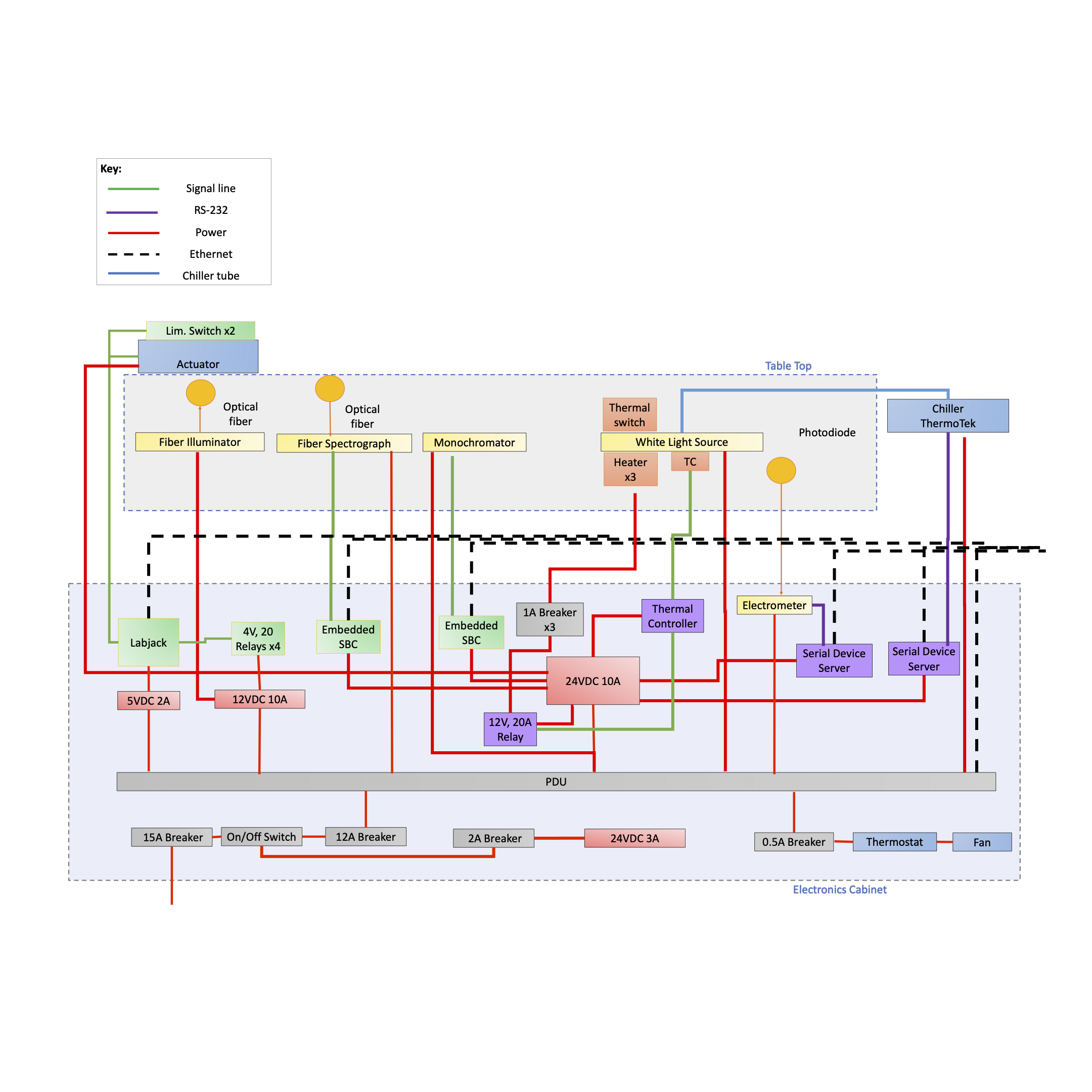
Figure 9 Functional diagram of AuxTel Calibration Illumination system.
Outlet |
Name |
1 |
24 V/Monochromator |
2 |
Fan |
3 |
12 V |
4 |
5 V |
5 |
Electrometer |
6 |
Fiber Spectrograph |
7 |
KiloArc |
8 |
Chiller |
Cable No. |
Name |
IP Address |
DNS Address |
MAC Address |
1 |
Controller |
139.229.170.14 |
auxtel-ill-control.cp.lsst.org |
00:01:05:3d:71:64 |
2 |
LabJack |
139.229.170.19 |
TBD |
90:2e:87:00:a7:a4 |
3 |
Electrometer |
139.229.170.15 |
auxtel-electrometer.cp.lsst.org |
00:90:E8:9B:2C:BA |
4 |
PDU |
139.229.170.12 |
auxtel-illpdu.cp.lsst.org |
0c:73:eb:b0:81:ea |
5 |
Chiller |
139.229.170.16 |
auxtel-chiller.cp.lsst.org |
00:90:E8:6C:55:4B |
6 |
Monochromator |
139.229.170.13 |
auxtel-monochromator.cp.lsst.org |
00:01:05:34:11:37 |
3.9 Structure
The white light source and monochromator sit on a table surrounded by black construction hardboard used to create a fully black environment inside. There are thru-holes on the table for the cables that run to the electronics cabinet which is secured below the table. The chiller is also secured below the table.
The linear actuator that drives the shutter sits on the top of the structure and must be disconnected before the top is removed.
4 Maintenance & Troubleshooting
4.1 White Light Source Connection
If you can’t talk to the LabJack over ethernet, you can connect directly to the LabJack with a USB cable. First, unplug the power cord from the LabJack and then run the USB cable from the LabJack direclty to your computer. To talk to the LabJack, you can use the Kipling software.
4.2 Opening Electronics Cabinet
In order to open the electronics cabinet, you must first power down the unit. Then undo the two screw tabs that keep it closed.
If you need to troubleshoot within the electronics cabinet while it is powered on, use a pair of pliers on the rod to turn on the power of the system.
4.3 Opening Box
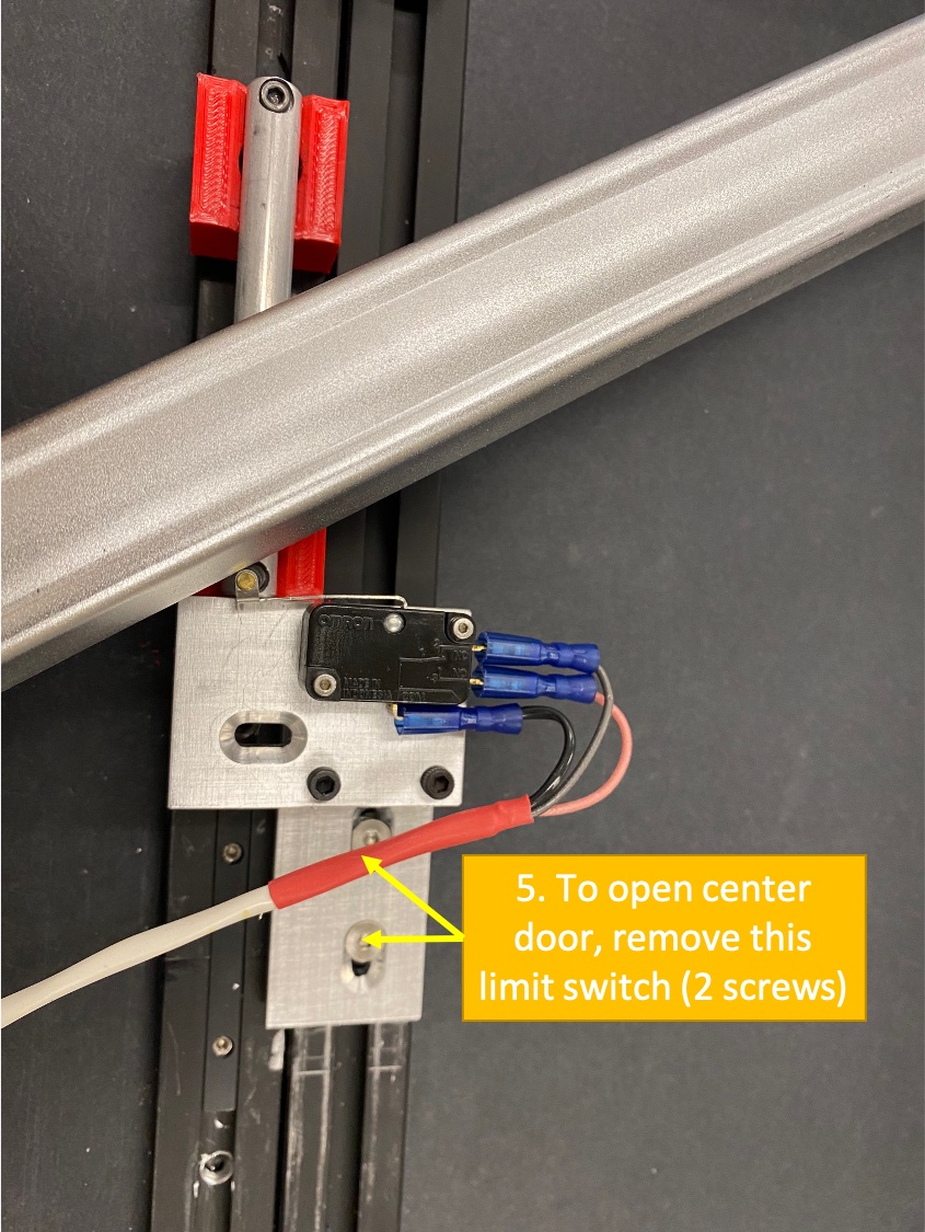
You may be tempted to open the box because there are handles on it and you want to look inside. If you do so without following these instructions, you will likely damage something. You can open the Left door at any time without damage. This is a good option for inspecting or adjusting the optics. If you want to open the center or right doors, following these steps:
Undo the wires to the “open” limit switch

Remove the pin and nut from the linear actuator
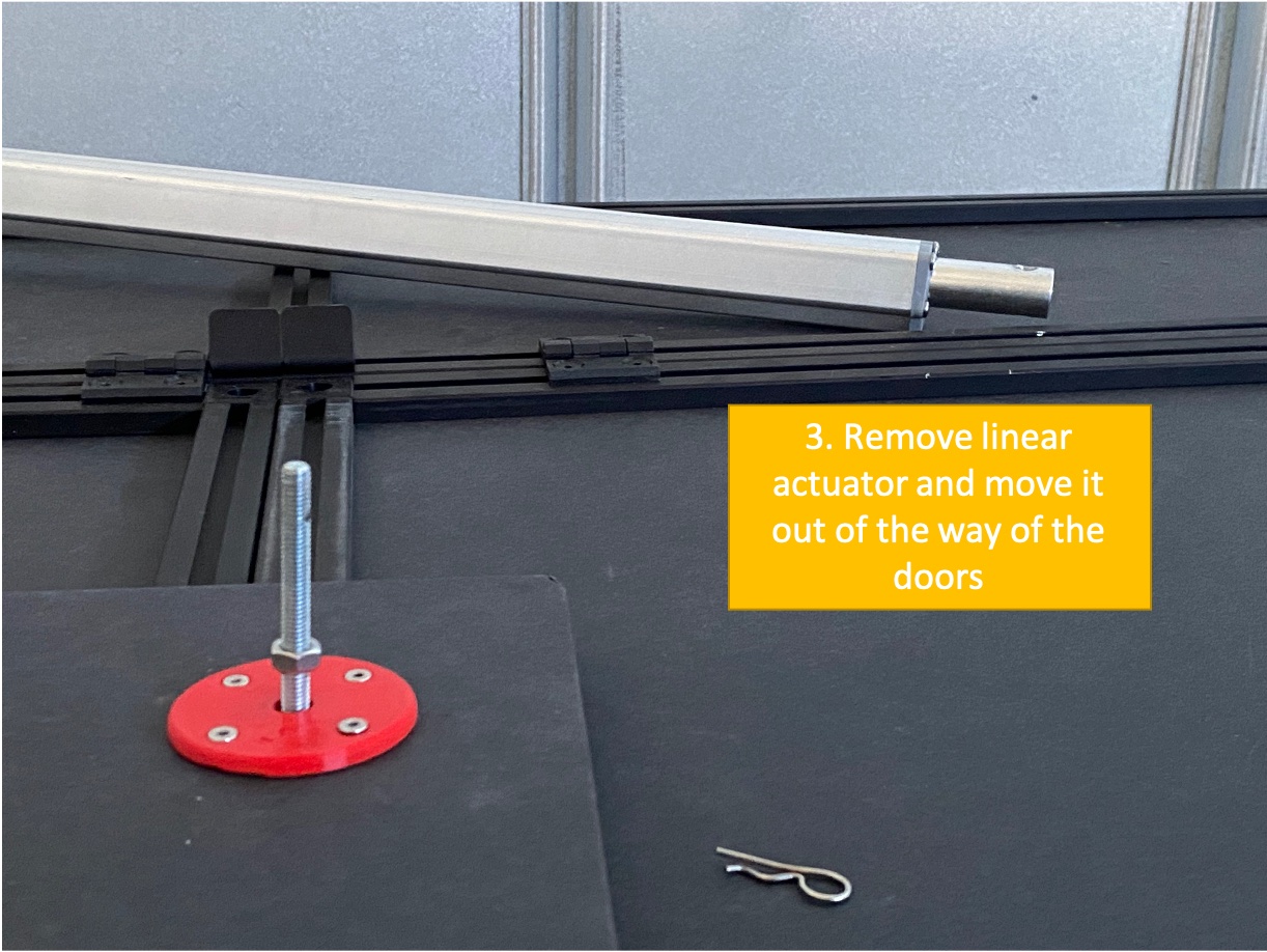
Remove the linear actuator and place it out of the way
Remove the final bolt on the shutter and remove the shutter
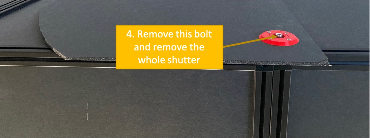
If you need to open the center door, remove the “closed” limit switch


4.4 Chiller Maintenance
You may need to refill the water in the chiller occassionally. This should be done with distilled water mixed with 10% of methanol. The total amount of liquid is approximately 1 liter.
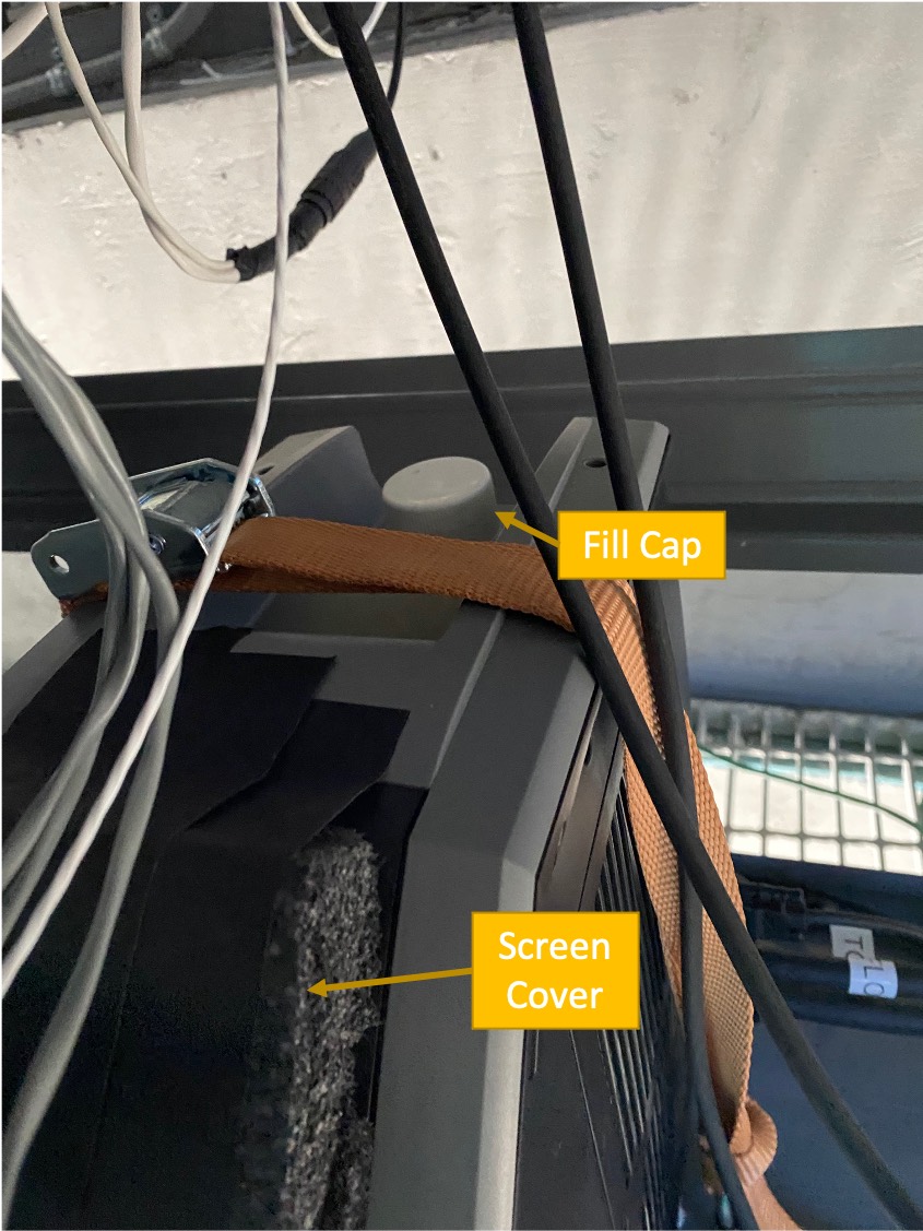
Figure 10 Chiller cap for refilling water/methanol mixture.
4.5 Using the Fiber Illuminator
You might want to use the fiber illuminator to calibrate the fiber spectrograph. This spectral calibration lamp will be kept in storage until needed. When you want to use it, follow these steps:
Open the right door
Plug in the fiber illuminator to power (12V). The power cable should be sitting right next to the monochromator
Remove the end of the fiber from its place in the optical path and install it into the fiber illuminator
Note
You may actually want to install an absorber between the lamp and the fiber spectrograph
Turn on the illuminator and take spectra with the fiber spectrograph
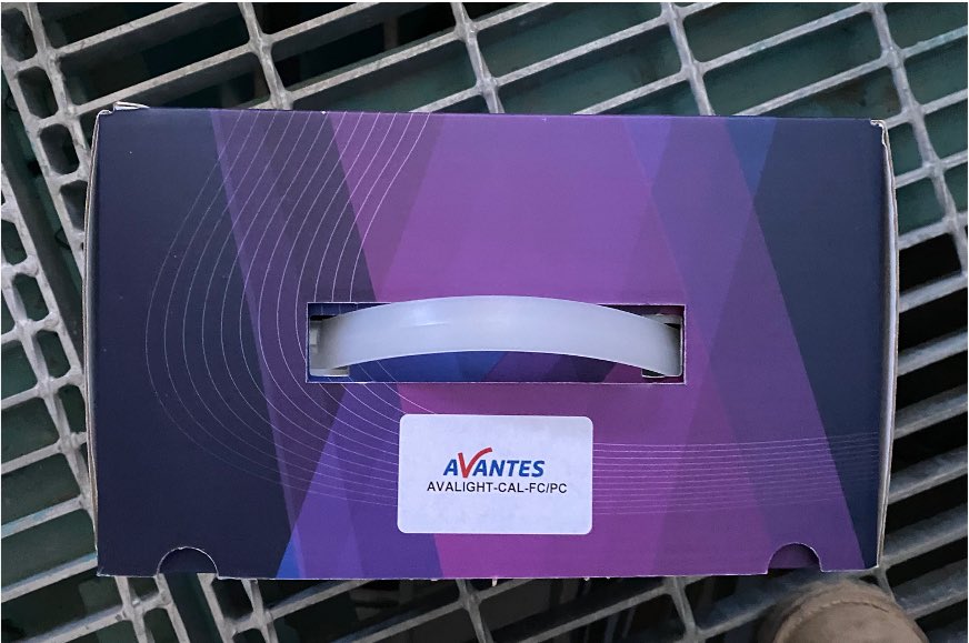
Figure 11 Fiber Illuminator, which will stay in storage until needed.
4.6 Monochromator Initialization
When the system, inlcuding the monochromator windows machine, is power cycled, you need to Initialize the monochromator before using. This can be done using Remote Desktop using the IP address listed above for the monochromator. The username is MONOCHROMATOR-PMonochromator. The credentials for accessing the Remote Desktop can be found in the AuxTel 1password vault.
When you’ve logged in to the machine, open the LabView program. This will initialize the monochromator. If you have issues connecting to the hardware, you may have to check the USB connection and power cycle the monochromator itself.
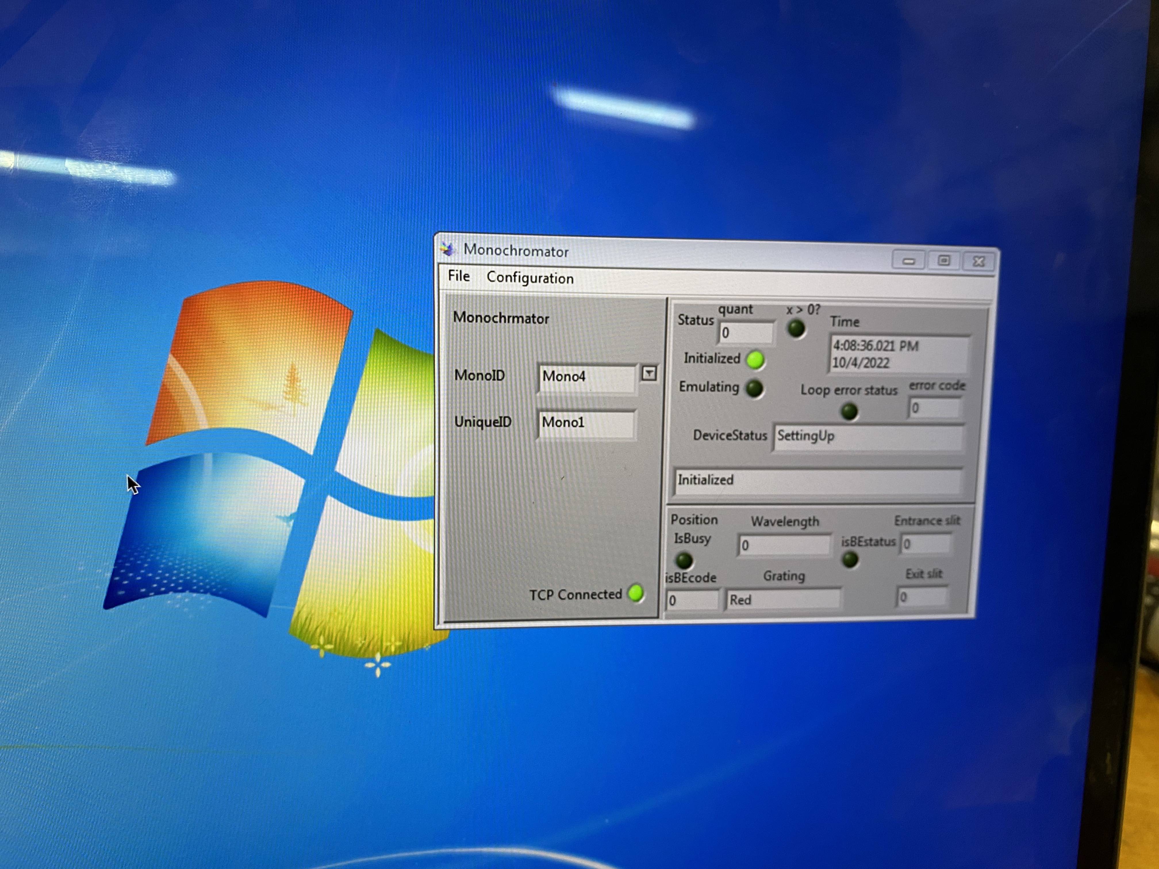
Figure 12 Screen on the windows monochromator machine when you’ve connected using Remote Desktop. It will say Initialized when ready to use.
If you cannot connect to the windows machine at all, you will need to connect it to a monitor, mouse, and keyboard. Please note that it can only be connected to a monitor using a DisplayPort connector.
5 Operation
Operation of the AuxTel Illumination system will be detailed and updated in the Observatory Operations Documentation https://obs-ops.lsst.io.
For initial functional testing, use the notebook in _static folder under this repository https://github.com/lsst-tstn/tstn-032/ as AuxTelCalIll_FunctionalTest.ipynb.
6 Initial Results
Several tests were run in Tucson before shipping this.
The notebook used to run these tests and do the analysis are saved in _static folder under this repository https://github.com/lsst-tstn/tstn-032/ as AuxTelCalIll_FunctionalTest.ipynb.
Below are the results.
The general conclusions are:
Takes 30 minutes to 1 hour with lamp on for brightness to be stable

Grating 0 should be used from 300 - 550nm and Grating 1 should be sued from 550 - 1150nm

Width of lines in wavelength ~10nm
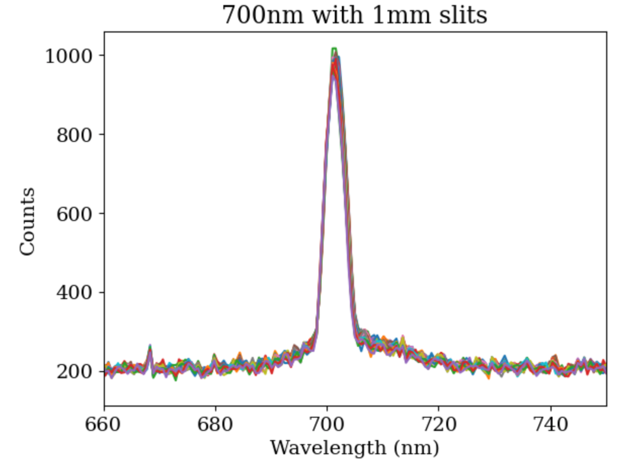
More work should be done on optimizing the slit widths per wavelength, but optimal will likely be around 1 or 2mm on both entrance and exit.
The wavelength offset seems to vary across the spectral range. This needs to be further investigated


